
Polar moment of inertia is analogous to planar moment of inertia but is applicable to a cylindrical object and describes its resistance to torsion (twisting due to an applied torque). The result is expressed in units of length to the fourth power: m 4 or in 4. The equation for planar moment of inertia takes the second integral of the distance to the reference plane, multiplied by the differential element of area. This is important because it specifies the area’s resistance to bending. Planar and polar moments of inertia both fall under the classification of “second moment of area.” Planar moment of inertia describes how an area is distributed relative to a reference axis (typically the centroidal, or central, axis). Planar and polar moments of inertia formulas Mass moment of inertia is important for motor sizing, where the inertia ratio - the ratio of the load inertia to the motor inertia - plays a significant role in determining how well the motor can control the load’s acceleration and deceleration.

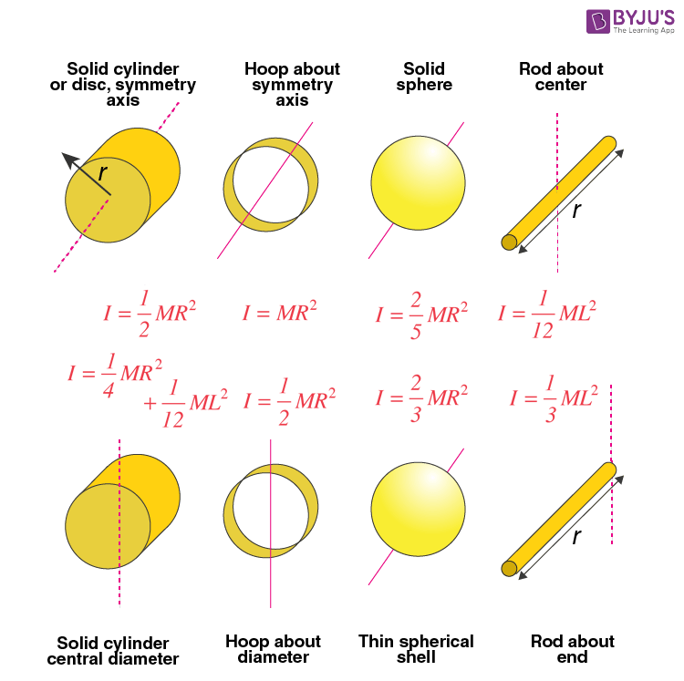
In many applications, an object is modeled as a point mass, and the mass moment of inertia is simply the object’s mass multiplied by the radius (distance to axis of rotation) squared. Its units are mass-distance squared: kgm 2 or lbm-ft 2. (Note that slug-ft 2 is also sometimes used.) Mass moment of inertia is typically denoted as “I,” although “J” is commonly used in engineering references, such as motor or gearbox inertia specifications.

Mass moment of inertia describes the object’s ability to resist angular acceleration, which depends on how the object’s mass is distributed with respect to the axis of rotation (i.e., the object’s shape). In order to know which one is needed for a given calculation or analysis, it’s important to understand the differences between them and how each one relates to the behavior of an object. The term “moment of inertia” is often used generically, but depending on the context and application, it can refer to one of three different moments of inertia: mass, planar, or polar.


 0 kommentar(er)
